WESTPORT TERMINAL RR |
Dec 2004 update |
[How to scratch build turnouts] and [crossings] [Manual thrown Peco turnouts] [switch stands] [Movable magnets] [DCC] [beacon light] [CB&Q 173] [RS-1 and weathering] [tender pick up 0-8-0] [ Track Cleaning Transfer Caboose ] [ Signal Bridge ] [Operation] [Way of Hopper BN 25 3 84] [WT RR industries shipping & receiving] download Excel [carcards&waybills] 900kB [staging] [Harbor District] [Plywood District] [Third Street Industrial District] [track scale, structures] [Operating gates] [Waterfront Structures] [trestle] [Interchange Cars] [car exchange] [pass exchange] [electronic rail pass ] [ video ] |
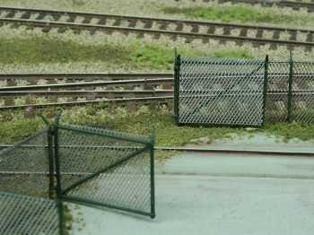
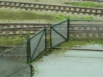
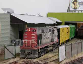
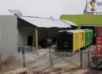
Operating gatesThis idea was published in MR May 2006 project illustrated Pictures are linked to a larger view, click on them. It was about 1990 when I build at my module “Naumburg” a furniture factory, called “MöbelFormAldehyde”. You have some Formaldehyd in chipboard wood. So came the name. It was very amusing to look at visitors. They recognized the gates opening and you could count to three, their heads went under the module – or they didn’t look carefully.
This factory got a gate for loading the cars in the house. And the area got a fence from Alloy Forms. Yes, I used at this time Alloy Forms for my German module. The fence needed a gate, too. And these gates had to be moveable. The operation of the manual thrown turnouts in “Naumburg” works reliably without motor or relay drive. This method is admitted for movements caused by muscle power accordingly. Like that it was only logical to remain further independent from strange energy sources with a purely mechanically design. One of these tasks which can be drawn constructionally was the gate mechanics for the “MobelFormAldehyde GmbH”. A crank drive for the gate movement was the first idea. But it was rejected as too complex. A simpler solution, as it had been in principle already found for the manual thrown turnout (first time published in Hpl model railroad 2/88): a connecting rod in connection with levers.
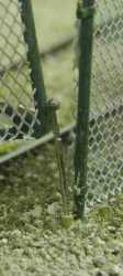
The gate hinge was maintained in the upper fulcrum, which is intended
with the gate from Alloy Forms. The lower hinge at the fence post
was removed and instead a 0.5 mm ( 0.0197’’) wire glued
with ACC into the eye of the gate. It led into a socket, made of 1mm
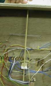
(0.039’’) brass tube. And now to the underground mechanics, whereby the sketch serves as guidance. As margin I fastened a piece of wire to this connecting rod (with
connecting rod pushed in) 4 cm (1.5’’) from the front
module edge. (drawing #6 and #8) Since both gates should turn over
90°, I drew two 90° angles on the module.
Important it is only that on the one hand the friction between guidance and lever arm remains as small as possible, and on the other hand the guidance is not sufficiently stable, in order after each opening and closing to have to make a readjustment of the gate.
If you use this mechanics at a shed gate, then there are different possibilities for the attachment of the 0, 5 mm diameter gate axle. Glueing is not recommended, since the mechanical force could be too big and the splice breaks. If the gate has a sufficient wall thickness (about 1 mm), then fasten the gate axle into an appropriate drilling, with thinner gates probably only glueing will be possible. Then however it is appropriate to bend the gate axle and to stick this increased adhesive surface as hinge camouflaged on the gate.
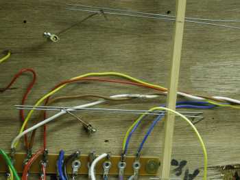
And at Diamond Valley has the oil dealer the latest version.With terminal strips you can adjust easy.
|
| [How to scratch build turnouts] and [crossings] [Manual thrown Peco turnouts] [switch stands] [Movable magnets] [DCC] [beacon light] [CB&Q 173] [RS-1 and weathering] [tender pick up 0-8-0] [ Track Cleaning Transfer Caboose ] [ Signal Bridge ] [Operation] [Way of Hopper BN 25 3 84] [WT RR industries shipping & receiving] download Excel [carcards&waybills] 900kB [staging] [Harbor District] [Plywood District] [Third Street Industrial District] [track scale, structures] [Operating gates] [Waterfront Structures] [trestle] [Interchange Cars] [car exchange] [pass exchange] [electronic rail pass ] [ video ] |